Now, if you have a Major in Geometry, this will seem easy. If you, like me, don’t have one of those fancy-smancy titles, then you’ll need to dig deep (not that deep really, but I definitely could’ve used an ELI5 on some of the things that now seems logical).

I started out by following Donut Media’s Zach Jobe in his “Alignment Explained (+ DIY guide)” – not going to embed it here, go there, click Like and support the Donut Media guys as they do awesome stuff. However, I had to do a couple of things differently – not sure if this is me doing something wrong or ass backwards- or it’s Zach jumping the lowest part of the fence (or maybe the gate was open). I can only tell you what worked for me.
Last things fucking first: Since I’d disassembled everything without taking notes, once kinda reassembled, I had an MX5 that was completely bent out of shape out of anything resembling alignment. The different guides on the net all says to write down the settings before taking shit apart. Well, do I look stupid to you?. I don’t need to do that, this is easy right? (Besides, everything was covered in sticky black goo, so getting any form of readings would be guesswork at best, so there!). Nowhere does it say how to start out if you didn’t write your settings down and used those as base settings, so I did the only logical thing (after many hours of contemplating and many “hmmms” and “one could maybe also”‘s) and set everything as close to zero without spending a million hours on it. Toe and camber as a priority.
Caster (front only):
MUY IMPORTANTE! Here’s a thing I found out when using the turning plates for measuring, and this may or may not work for you depending on your wheels: I would get the same number if I used the Tenhulzen plate to measure the angle with the angle finder in the plate like this:
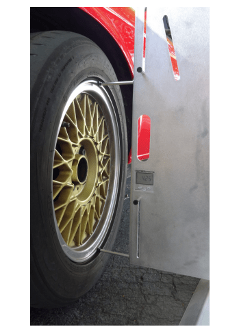
or if I just placed the angle finder on the center cap.
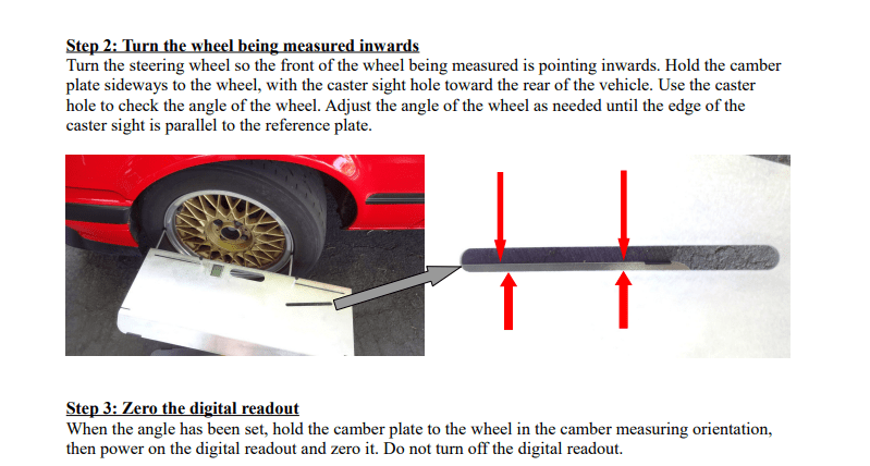
As Zach correctly (because: geometry) says in the video, you start out by adjusting caster. This is not too complicated once you find out what you’re doing. If you start with the left front wheel (front, of course, there’s not caster in the rear), you turn it 20 degrees to the right, zero out your angle finder on the wheel, then turn the wheel 40 degrees to the left and measure the angle again and multiply by 2. That’s your caster number – simples right? ¯\_(ツ)_/¯
Aaaand Action: In a whim, whip up a set of turning plates a-la Zach, turn the wheel to one side, zero out, turn to the other side, measure angle again, adjust and Bob’s Your Uncle right?. Not quite for this old dog:
After I made the first set of turning plates, I simply didn’t trust the numbers I got when measuring the angle. No matter how many times I tried, re-setting the plates, turning this way then to other. It was no good. I could not get any consistent numbers. So, set number 2 was made. This time larger with more care taken and more lines to align them beneath the wheel. Still no fucking good. I still could not get the same number two times in a row when repeating the procedure (lather-rinse-repeat FFS). So on to phase two: Now, the first thing I did when I bought the MX5, before I found Zach actually, was buy a set of the Tenhulzen toe plates with angle finder and 2 x tape measure (which were immediately set on fire and thrown to the ground as they were inches onlyNote:1) as I knew I’d be doing alignment myself (“Be prepared, that’s my motto”). They can also be used when setting caster so out come the instructions from Tenhulzen. But because my car was on blocks and not on the ground as in the instruction video and pamphlet, I had to get creative with painters tape:

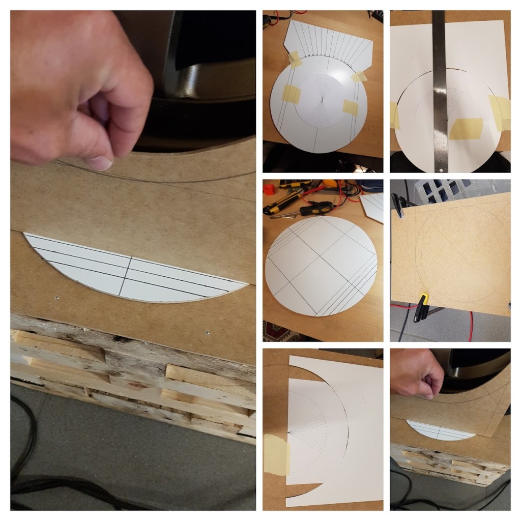
But, same same as with the turning plates. I still couldn’t get consistent results and this was seriously starting to piss me off! Sitting in grandmas chair in the garage (NO, she doesn’t live in the garage, she’s dead, we just got the chair) pondering how to best set this thing on fire without burning down the house, I spotted, in the outbox destined for scrap, an old Ikea frame with a checkered background and Hey!, that odd moment of clarity you experience once in a blue moon.

As simple as copying the angle from the Tenhulzen plate, doubling it and using it for the pointy end of an arrow and you get this:

Used half of the backing plate as base for the checkered sheet and the other half for the arrow thingy. The angle of the “arrow” is taken from the Tenhulzen toe plate and doubled (40 degree). Now THAT requires a “Simples” ¯\_(ツ)_/¯
Instructions should not be necessary but: Make sure the checkered board is aligned with the wheel (use a ruler from the edge of the wheel to a line on the board) before you secure it in place, put the arrow on top, turn the wheel until the first of the angled sides lines up with the board, zero out your angle finder, turn the wheel the other way so the other angled side of the arrow lines up, measure the angle of the wheel, multiply by 2 and there’s your caster. BOOM: Headshot. With this, I could get consistent numbers 10 times out of ten!.

Then it was just a matter of adjusting the rear bolt holding the lower control arm until you get the desired number. I think Zach mentions in the “Answering Subscriber Questions (50th Ep Special)” episode of Moneypit, that he would’ve gone higher with the caster, so I went with 3 (that makes the caster number 6 – multiple by 2 remember?). (He also mentions that had he known then what he knows now, he would’ve outsourced the alignment… I’m thick skulled, so I didn’t but having learned a new skillset makes it well worth it).
Camber – Front:
But first, why I think Zach said something wrong:
Now: There is one place where I’m positive I’m right and Mr. Jobe is doing something wrong, purely based on simple geometry. When he starts working on setting the camber, he tells you, that if the car is on an uneven surface (which makes matters worse actually), you can zero out your angle finder on the block the wheel is sitting on: Here’s why I think that’s a big-ass fucking no-no:
When you zero out your angle finder on the block the wheel is sitting on, you’re zero’ing it our relative to that particular place on your uneven floor, not relative to the car (which is what you want: You want 1.5 degree negative camber relative to the car, not to a single spot on the floor). Let’s put some numbers on my ramblings:
If your blocks are 35×35 cm (WxD) and 30 cm tall (could be 2 meters, this number is irrelevant) and it’s tilted, because your floor is uneven, by say, .3 degree left to right, that’s means one side of the block sits 1.833 mm higher than the other. This then means, that if you use this block to zero out your angle finder, it’s zero’ed at .3 degree, relative to that specific place on the floor, not relative to the car which is what you need/want. If you instead use a straight bar that goes from the left block to the right, if you include the height difference left to right on the tilted block, you get a zero’ed out value of 0.07 degree instead, and this being relative to the car, not to a single point on the ground.
The numbers above could reflect a real word scenario, but they’re too small to do well on illustrations however, so let’s turn the numbers up to 11 (Why not just make 10 louder) so we can get something visual (I said it before, I’m a visual guy). This time we tilt the offending block by 2 degree instead of 0.3, now the difference between the left and right side of the block is 12.15 mm. If we use the bar covering both blocks, we’d instead get a reading of .43 degree and not 2. Obviously the tires being flexible would mitigate some of the unevenness caused by the 2 degree tilt in the right block, so let’s say that take out 2/3rds of the .43 degree, that leaves the car with a tilt of .14(‘ish) degree which would leave you with a real world camber setting of 1.36 if you’re aiming for 1.5 degree negative – if you went with the angle finder zeroed out on the 2 degree tilted block, you’d end up trying to push around 3.3 degree negative once the car is on an even surface (pretty sure my calculations are correct).


With that out of the way, on the front, it’s a question of adjusting the front bolt holding the lower control arm until you get the desired number. Mine is an NB and they’re not quite as willing to go as high as NAs. I’ve seen posts where people couldn’t get them above 1.5 degree negative. I was able to get mine to 2 on both sides.
20210928: This will be updated once winter is here and it’s back on the blocks. The above information is not wrong, but there might be a twist that I (and obviously Zach too) missed by not reading the factory manual in the first place! (Did you know, just 4 hours of debugging can save you 20 minutes of reading the actual manual?)
Toe – Rear:
Why not set the Camber in the rear after the front as Zach does in the video?. Because the official Mazda manual says so

- and because I had a great time figuring out what was going on blindly following Zach!.
Now. Since I don’t have a fully fledged shop with friggin’ lasers for adjustment, I did this using the string box. Zach explains how to make on and set it up better (and faster than I can). There is a small note for those of you starting from scratch: If the camber on your rear wheels is out of sync, so will your string box be. Here’s the rear wheels with 0 degree camber on both sides, meaning your string box will be straight:
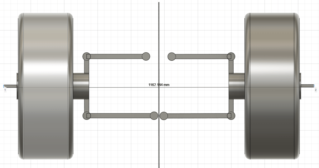
But look how much out of line your string box will be if we add just 1 degree of camber to the left wheel:

That’s 2+ mm which means your string box is now all fuxxored and all the toe readings you’ll get will be out of whack (so says the youth of today) And that’s with 1 (one) degree. So make sure your rear wheel camber is ballpark equal before you start building your string box. Same goes with the front, but those should be aligned by now.
With the box in place, there’s not much to adjusting toe in the rear. Turn the front most adjustment bolt outwards, you adjust towards toe-out, turn the rear most adjustment bolt outwards, you adjust towards toe-in. Turn the front most adjustment bolt inwards, you adjust towards toe-in, and finally, turn the rear most adjustment bolt inwards and you adjust towards toe-out. I did both at the same time trying to get the numbers as equal as possible (I don’t want to think about the number of times I got down on the floor, adjusted, got up, measured front and rear on the wheel, then lather-rinse-repeat ad nauseum). I ended up with -0.77 mm in one side and -0.84 mm on the other.
Camber – Rear
Simples, adjust front and rear bolts outwards the same amount at the same time for moving towards (or adding more) negative camber, inwards for reducing negative or moving towards positive (we don’t want that).
Now, I did say simples, and it is, it just takes a lot of tries to get it spot on. I went with 2 degree negative to match the front.
Job jobbed, as the kids say today.
I think that’s it basically and concludes my learnings for doing your own alignment. It’s a pain in the proverbial behind sometimes until you figure out the ins and outs and do’s and don’ts.
Note:1 on the Imperial System: Because: “Does this look like 5/8’s?”; “Naaah. That’s more like 7/16th’s” makes about as much sense as:

Fucks sake it’s stupid (apologies to all who find this logical and thinks the metric system is the work of the devil. You’re still wrong though)….
