Doors and Corners, Kid. That’s where they get you. (Miller)
Something about doors at least. I’m not trying to be completely OCD (or am I) about this loom cutting business – just to save a few grammes. However – having first removed the door cards and realized how much wire, and how thick, was in there, just cutting off the not needed part was never going to – ehhrm, cut it. So after having finally managed to remove the connecting rubber thingy and it’s mounts (which is another exercise in swearing) the solution was pretty simple. Keep the stock rubber thingy. Remove the clip from the door side and the multipin connector from the body side and replace them with simple squishy things.
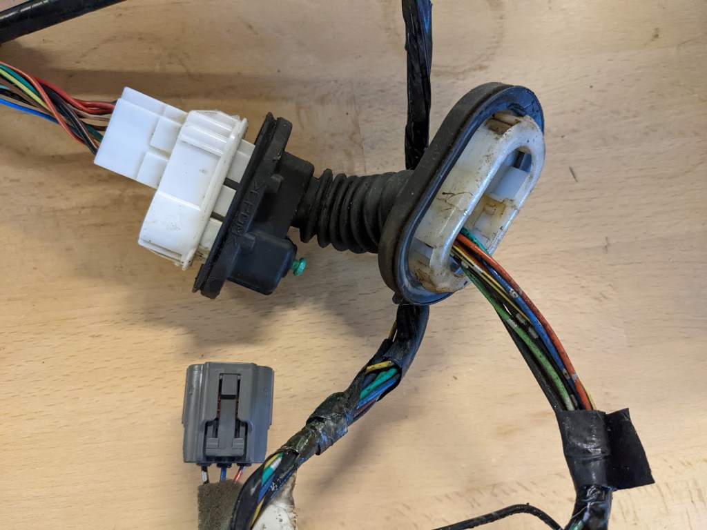
Standard body to door connector thingy full of yucky stuff.with all the wiring that goes into the door. Speaker cable has already been removed here so this is technically not everything that’s going away.
So – an hour and a half or something in Fusion360 and out of the printer comes these:
They will be printed in some carbon fiber induced PETG before final assembly.
And mounted with a 5 core 1mm2 multicable – figured the outer sheath would hurt since there will be some movement.
So much easier on the eyes than the standard part – should drop a few grammes as well.*
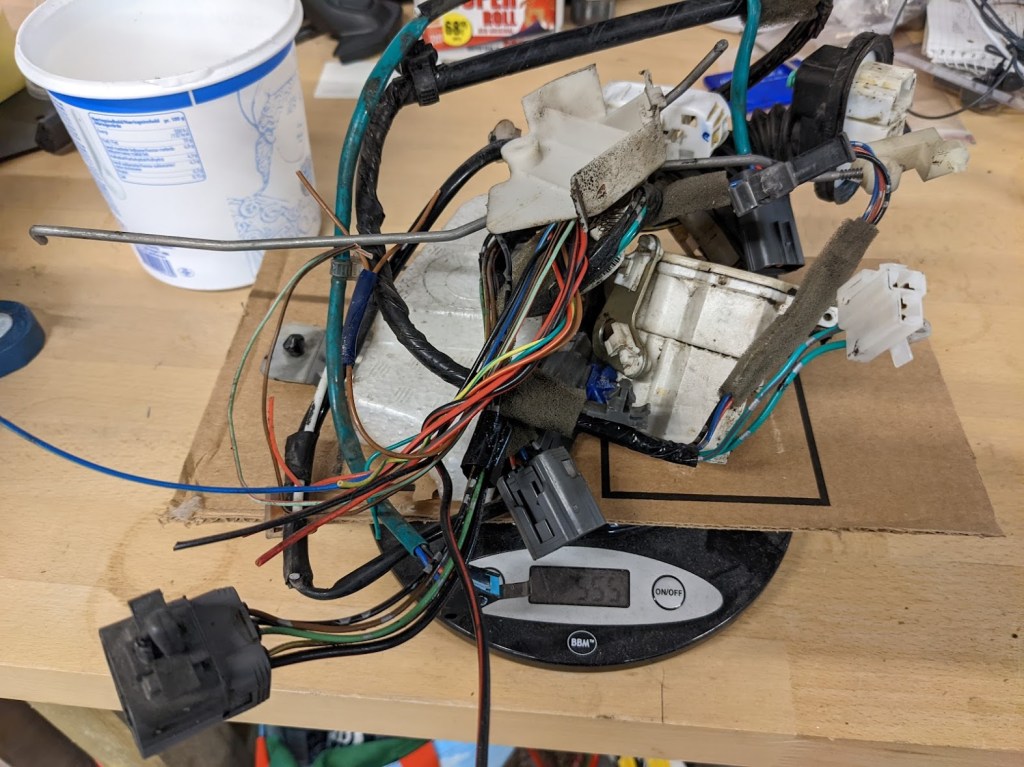
*Couldn’t let that stand, so here’s everything removed from the passenger side door (minus speaker cable) including the motor for the central locking system.
555 grammes (it was zeroed out with the cardboard) – so realistically, including a short piece of the 5 core cable, we’re looking at a saving of at least 800 grammes. JUST wiring for the doors. (as said, I try to not be too OCD about this weight saving program)
I have a million little projects going on at the moment. Most of them doesn’t really need a full-on post that takes me forever to write, so now I’m going to see if I can’t put some of my ramblings into smaller posts. Once again, they will (probably) not appear in the order they happened in real life.
Since this is the first of these … ” Blogging things “, I have no idea what it will look like, so I’m going to add two very interesting pictures of cables…
This is what has been removed so far – this is not going back in the car.There’s your problem (obviously)
1. Security (and not Through Obscurity – it didn’t work for Cisco)
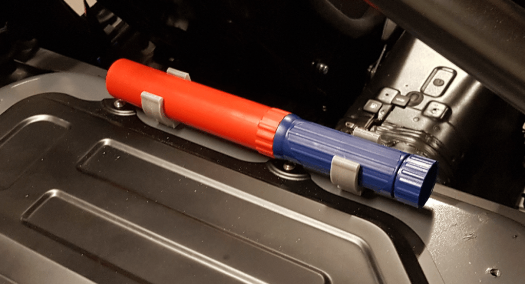
Instead of hauling a 6 kg fire extinguisher around in a car where you’ve been over every nut and bolt to see what doesn’t make it stop, turn, slow down – and keeps you alive, seems like a pretty dumb idea. Still, having one within easy reach seems like a good idea so when I stumbled over the Fire Suppression Systems 100, that was pretty much a no brainer:
and it weighs in at a whopping 550 g.
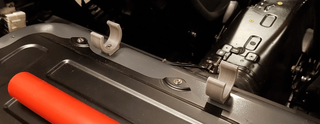
An hour of Doodling in Fusion 360 and Bob’s Your Uncle:
Fingers crossed I’ll never have to test it, but nice to have it readily available (I’ll print another set of clips so I can keep it in the trunk if I have to park the car unattended.)
2. Progress on mounting the hardtop
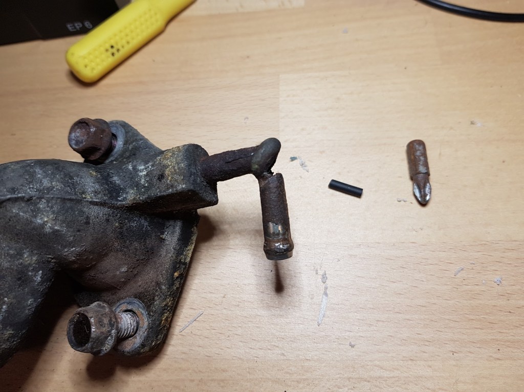
Still haven’t as much as test fitted the old blue hardtop I bought ages ago. 1: There’s been no need for it yet. 2: I’m a lazy and procrastinating bastard. 3: I Need to get the latches sorted*. 4: The strikers doesn’t fit because of the rollbar.
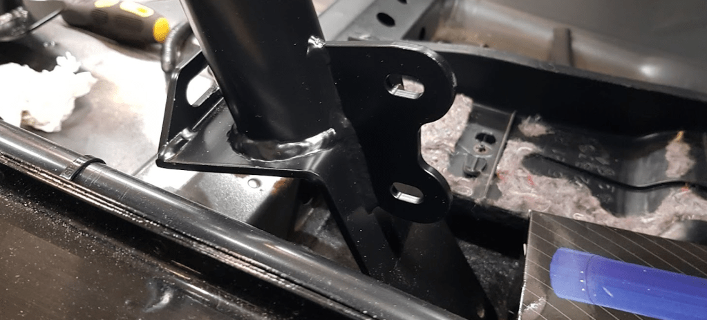
Now I’m no metal artist but think I did ok on cutting down the strikers for the latches so they don’t interfere with the rollbar:
One out of 4 issues solved.
*One of the latches were missing a pin – quick email to Andreas from Au2fast for getting me one in less than 48 hours! Once again to the rescue.
3. Speaking of rollbars – replacement with eyes for door bars also in place.
Got a replacement rollbar. Even though I ordered it with the door bars (because racecar), Cybul managed to ship the Roll Bar X without the eyes the door bars bolts to. Was given a couple options. They could send me a set of eyes and I could have someone local weld them one. They would also give a mighty discount on my purchase – or they could send me the correct rollbar and I do the fitting myself. Since I’d already done it once, that was a no-brainer. Since they agreed to arrange for pickup of the “wrong” one, that was just the cherry on top. Huge Thank you to William from Jocks.dk for getting this sorted. (Option one was never eve considered. Getting a discount is all good, but then having to clean up the area where it’s going to be welded, and not just clean up, remove powder coat etc. Then finding someone local to trust with the welding – not happening. And it would never look as good again.)
Anyway – much ado for a set of eyes:
How I managed to get the old one in and secured using a 17mm spanner on a 16mm bolt we’ll never know. I do know that it didn’t come out with that combo #Facepalm
4. Out and About for the second time:
This Sunday I did an 80 km, ehhh—, blast is probably too strong a word, a bit more Spirited than last time then, drive. I am finally falling madly in love with this car because 1. It handles just like I was hoping it would, and 2. once more nothing fell off or caught fire (had the fire extinguisher this time though!) or exploded and killed me while doing so. Took the BIL for a spin (of course he got to drive) and he said, unprovoked, that it feels like a completely different car from the wallowing Sunday drive cruiser we took for a spin when we first went to see it – Thank you Kind Sir because: 1. That was the idea – and 2. I did this – all by myself.<- there is no sarcasm in there!
Such a pretty little car (rear fender will be cut shorter shortly.)
I wanted the headline to read “Karen”, but out of respect for all the Karens who aren’t Karens, I let common sense prevail….
As mentioned earlier, I’m scared shitless of electrickery. Despite doing a 4 year apprenticeship at a company that dabbles in the manufacturing of audio and video gear, (that was back in the stone age when an amplifier required a huge solid core transformer and televisions were all CRT), to this day, I have an strong and deep rooted distrust of electricity. I’m fairly sure I have a somewhat decent understanding of all (basic) things electric – and that I usually have a pretty good idea about idea about what I’m doing (at least it’s been though through and pondered over for hours). So it’s not that I don’t trust my own skills and understanding of electrickery – it’s the electricity itself I don’t trust.
With that said, there were still a lot that needed to be done to the old girl – electrickery wise:
It came with heated seats and the assortment of wiring, wire clamps, switches, fuses etc. etc. that goes with them. That had obviously had to go since we’re doing bucket seats.
It also came with a heated rear window in the soft top. Had to go (both parts)
Even better, it came with an aftermarket Cruise Control which really had to go.
It came with speakers. Those had to go incl. the wiring and most of the wiring for the stereo as well.
Has an electrical aerial. Cables for motor and signal must go along with the aerial itself.
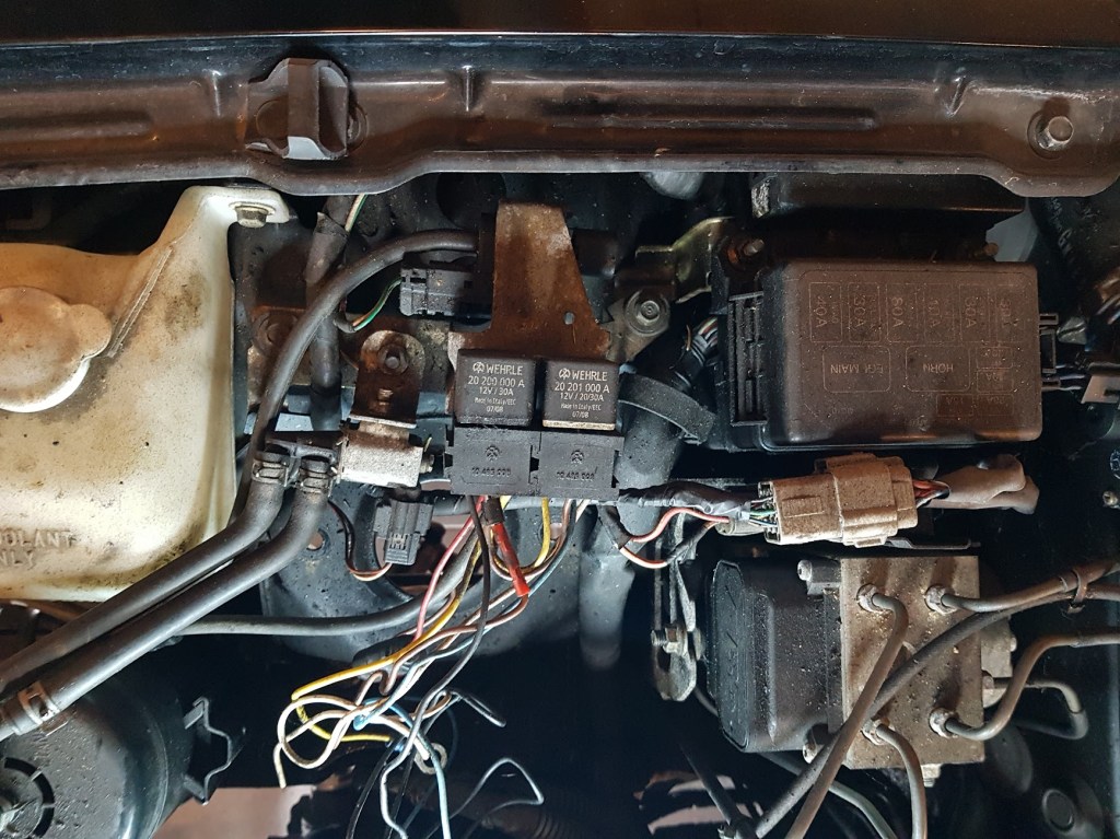
A couple of relays in the engine bay also looked a bit “odd” – could those go?.
Getting rid of the center console meant the switches for the power windows had to be relocated. I thought about getting rid of the electrical windows all together (KISS), but realizing the weight of the mechanical setup is basically the same as the electrical one, decided on a pass for that option. (it would also mean a ton more work which I didn’t need)
1-6 are mostly getting rid of stuff and looking at poor craftmanship, so let’s do 7 first.
Center Console Delete (#7)
This is the final result (minus being prettied up – Once it gets a coat of spray filler and a bit of matching, more or less, color, I reckon it’ll look half decent)
Doodled in Fusion 360 and printed on my old Anet A8 (yep, the one that’s famous for burning down peoples houses. I bought this maybe 5-6 years ago and it has served me with no issues whatsoever since. Reading as of right now where it’s printing an iPhone holder for my BILs DoKa says it’s printed just shy of 8 km of filament without burning down the house). Unfortunately … The A8 is not a large area printer, 220x220mm, so I had to design it, then split the part into two halves and print them separately. It worked out ok but it’s probably 5g I could save in 3mm nuts and bolts and glue and shit, so it will be rectified eventually. (If you know anyone with a larger than Anet A8 print area, please ask them if they need a new friend).
Last count tells me I did 17 prints until I was happy (and idiot me realized that a single pole switch wouldn’t work so add another print to the pot) – at 8-9 hours a print, it took a while. Luckily I’m a patient boy/man/old person.
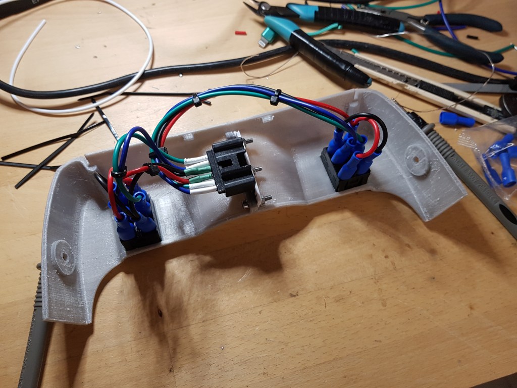
For those interested, the wiring part is actually super simple – all you need is a pair of DPDT (Dual Pole, Dual Throw) temporary switched (meaning they don’t stick in any position except null of course). I stole the female connector from the factory switches so the Center Console Delete piece can be removed by unplugging it.
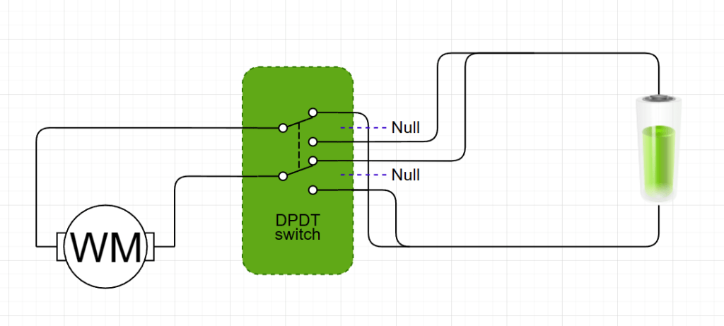
As for the wiring/schematic – this should give you an idea and an explanation:
You have the WM which is your Window Motor and in the middle, the DPDT switch. Imagine the purple dotted line is the switch’s null position (draw.io didn’t have a suitable one, sue them) where nothing happens. With the above, it’s basically self explanatory: Connect +/- to the outer terminals on one side of the DPDT and use the common for the motor. Then do the same on the other set of terminals on the DPDT, except flip +/- of course.
That’s it basically, question or comments below.
Yes – the 3MF files are right here – they take up very little space, so there’s all 4 files in there. Full panel with and without cutout for switches and left side with and without cutout for switches (In case you ask me to upload the Right side of the CCD, it’s time to step away from the 3D printer)
Let me just post some pictures, because, why the hell not:
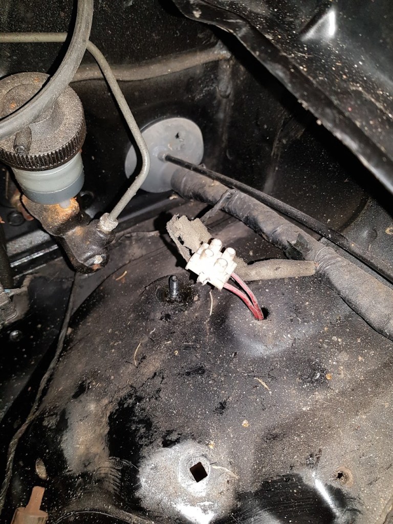
This is what the wiring for the Cruise Control looked like. Notice the 200g metal bracket for holding the disable switch that’s activated by the brake pedal. Work of art if you ask me!.
This is how they stole the signal from the speedometer. Don’t have a close up of the connection with the tape removed, but it looked something like this:
Only a bit smaller. Remove the insulation from a cm of wire without cutting it, then wrap the new bit around like 4-5 times and then smother it in soldering wire. It’s going to hold no doubt, but removing it without burning the wire was an exercise in restraint.
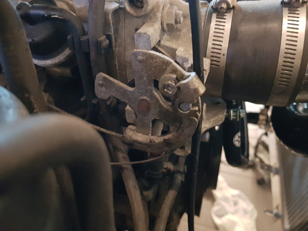
This part isn’t strictly electrickery but the business end of the the Cruise Control. Notice how the second throttle cable (yes, it was a mechanical CC) is attached with what looks like a wood screw. I can deal with a lot of things, even stupid people. What I can’t deal with is sloppiness. If you want to do something, either do it right or don’t do it at all. Half arsed jobs gets me like nothing else.
In the end – this is all that was removed with the CC (control device thingy weighs a kg or so alove)
Something on heated seats perhaps?
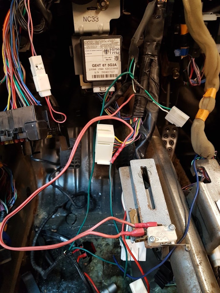
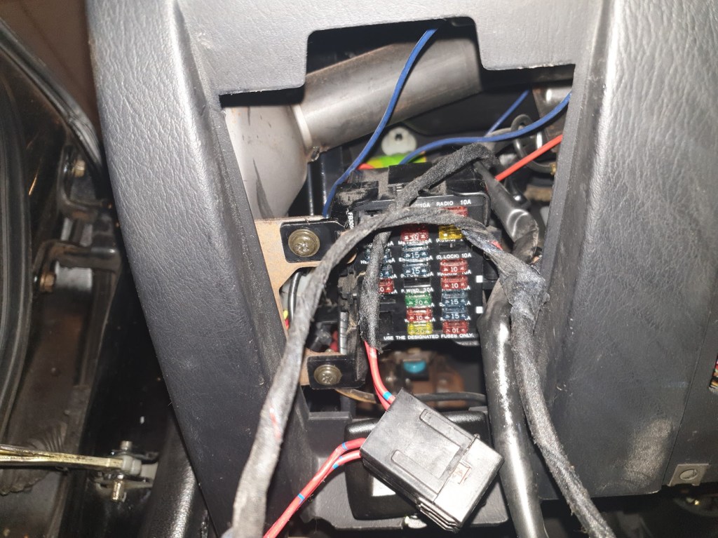
This is how you steal power for your heated seats. The black box is a fuse holder. Those can be free to rattle around – it’s perfectly fine.
This is after I started pulling the wires you see coming from the two relays. They were stuffed in beneath the relays and once I pulled them out, turns out, that only a single wire from those two relays were connected. And that was to ground. Some ping pong with some nice virtual internet people and we decided that at some point, some mong who shouldn’t have access to tools someone smart decided to make a automatic running headlights and they either couldn’t get it to work and decided to just leave the pieces in there because fuck it, or it broke at a later point and whoever sorted it decided to get rid of the automatic running headlights without removing the actual parts because, fuck it. Anyway, it’s all gone now.
I’m guessing the old gal started life as the cheapest model possible and then:
No heated seats // Easy fix, look here: *Burns driver and passengers’ bottom*
No cruise control // Easy fix, look here *Crashes car with stuck throttle*
No automatic driving lights // Easy fix, look here *Burns the entire car*
No aircon – Luckily no-one decided to “improve the situation”
How it managed to survive – No idea but duly impressed.
This goes to the driver side indicator and was located beneath the shoebox sized control module for the cruise control – that’s not how you do wiring in a car….
Final Words
ok. So this wasn’t strictly (or as much as I’d liked) on electronics, but sometime later, over winter probably, there’ll be a lot more talk about electricity. I have a cunning plan for simplifying the whole making a new harness and getting rid of everything not needed. The standard loom contains e.g. all the wiring for the a full AC system, wiring for factory Cruise Control etc. that I will never need. There’s also multiple places where the wiring is redundant which could save a few grammes as well. We’ll get to that in due time.
To be cont’d.
Almost forgot: As standard, the main 12v wire going from the battery to starter/starter solenoid is routed beneath the car strapped to the PPF with the wires for the reverse and neutral switches coming from the gearbox going the same way. Those were moved into the car instead. Below the right side door (passenger side in my world), there’s already a plastic pipe that easily takes all of them. There’s even a hole in the firewall that fits the 12v cable incl. rubber grommet, so why Mazda decided on the other solution, no idea.
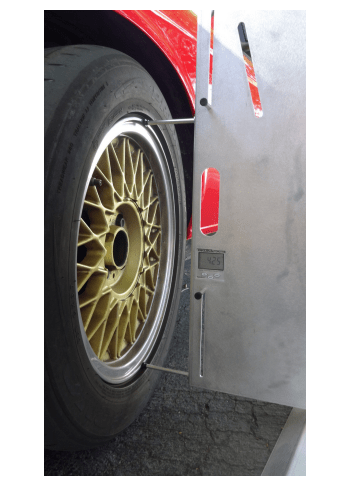
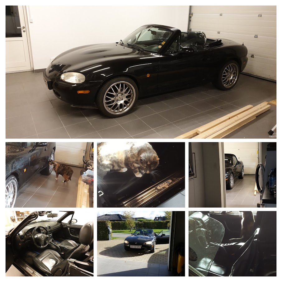
I can hardly believe it myself, but the MX5 is finally outside after sitting (not neglected, mind you) for the best part of a year. IIRC, I think it arrived home on the 6th of October 2020.
Do notice that the black coating on the brake disc is gone – yes, it’s been driven! ( :
Anyway – Since I managed to Snatch Defeat from the Jaws of Victory, life got in the way. 6 booked weekends with family stuff. Almost a full week away from home doing work stuff, extended w/e away from home for Mom and Dads 50s Anniversary. Countless evenings spend planning some light entertainment for said anniversary and even more evenings doing a sign for it. Note:1
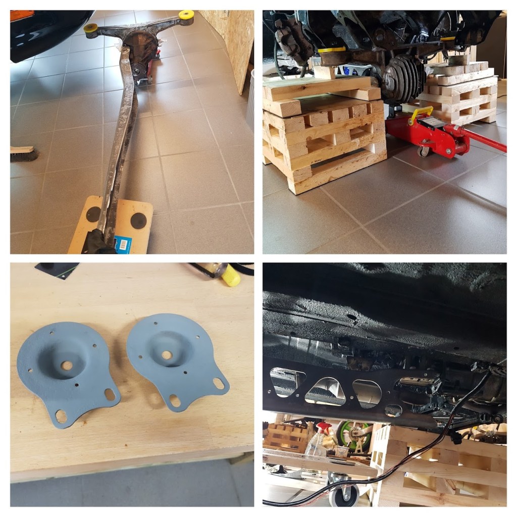
Still – this Friday, despite not feeling all that great, I managed to get the new housing for the water pump installed, got the prettied up subframe mounted (I honestly can’t believe I didn’t take a single picture of that) and got the new center console delete piece with switches for the power windows installed: Note:2
Odds on that part coming out again any time soon to be prettied up and color coded?. Slim to none most likely. The fit is ok and most importantly, the windows work. Go me!
So another Saturday away from home and then:
one MX5 leaving the garage under power, it’s own even, on Sunday the 26th:
Not sure why SWMBO decided to film in potato quality ( :
I’m a huge fan of loud pipes. Bikes, cars: something fast passing me on the highway doing illegal km/h makes my hair stand up. And the old saying: “Loud pipes save lives” – I’m a fan. Now the Japspeed 2½” stainless cat-back system is borderline ridiculous though. I don’t think it’s any louder than the stock, but has a bit of a burble that the stock one misses. I’m ok with it though. It doesn’t attract attention and it will definitely help give that vital good first impression come inspection date.
Anyway: I must have done something right because it feels awesome, it really does. I think the word I’m looking for is “tight”. Everything feels somehow solid and connected and not nearly and harsh as I had feared/expected with the HSD COs with 12 and 9kg springs (stock is 8/6). Mind you, they’re set to the softest position as they should be according to the manual for the first couple of hundred km but I was still expecting a much harder ride when adding 25% to the springs. It’s in no way plush like the stock MX5 (and no comparison with our VW up! at all) but I’m still surprised how it feels going over imperfections in the road.
Combined with the 3kg saved pr. corner going from 17″ to 15″, new spark plugs and spark plug wires, it also feels quite a bit sprightlier than before.
More plus: I really think my alignment is better than just ballpark. It tracks completely straight. Going left or right feels exactly the same – except opposite. When hitting the brakes hard with no hands on the wheel (you know what I mean), it doesn’t deviate. Just goes straight. Yes, the brakes are awesome too ( :
Only issue after the initial test drive to see if it would kill me or catch fire, or both, was the t-clamp on the top coolant hose that needed 1½ turn to stop the coolant pissing out. Refill and all was well.
And I did it all by myself – I could not be happier!
Note:1 I don’t do standard, so my take on a sign for a 50th Anniversary looks like this:
Note:2 I’ll get to the center console delete piece with the switches soon. Also Note:2 – if you want to take pictures of parts on the underside of your lowered car, do it while it’s sitting on 35cm tall blocks – not when it’s on the ground. Truth Fact!
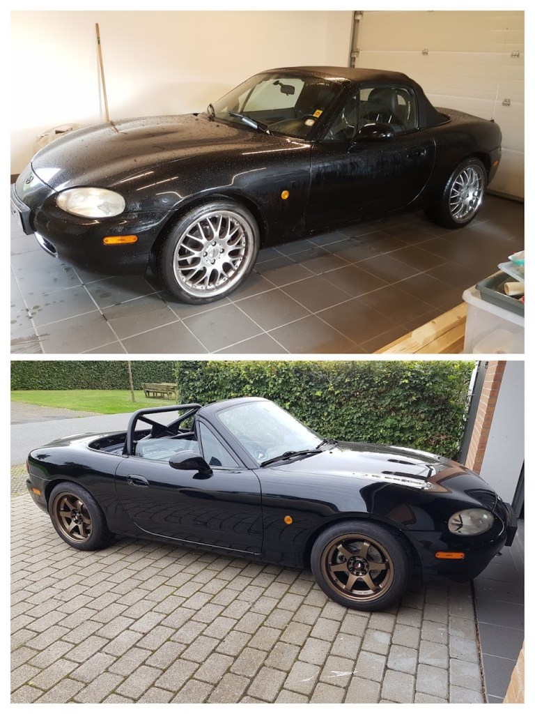
If you didn’t know better, you’d think some schmuck put in a roll bar, slapped on some 15″ wheels and dropped it 25mm… (that’s exactly what I did, more or less)
If you can’t be arsed to read all this, there’s some useful (I hope) tips on removing bushings at the end.
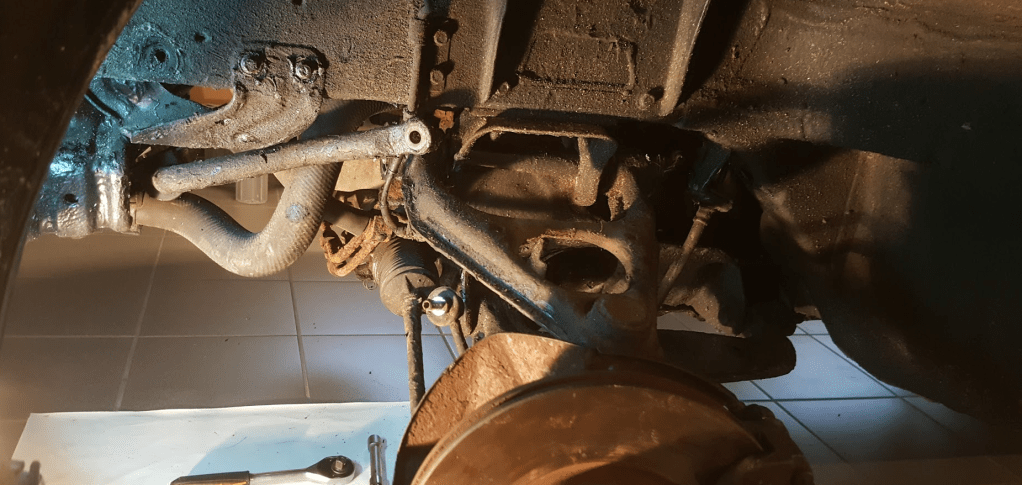
This is going to be extremely boring. The first month of ownership at least was one aggravating exercise of lather-rinse-repeat until you’re just about ready to say “Fuck this” and light the thing on fire. Now, don’t get me wrong, I’m all for taking care of your things, and if that means covering the underbody, every single nook and cranny and every moving part related to the suspension and drivetrain in a black sticky mixture of tar and God knows what else, by all means, knock yourself out. Right up until that very moment when it becomes my project car and I start tearing into it and I have to spend spend countless hours with a Windex bottle with the actual Windex replaced by petroleum, a brush and 5000 square meters of old rags..
Nice ehh?
I was just about ready to unleash a very particular set of skills I’ve acquired over a very long career on the guy who sold it to me, except, I didn’t really have to since I kinda knew who he was and where he lived. Besides, I’d already given him all my money and the car was on stands so how would I get there?….
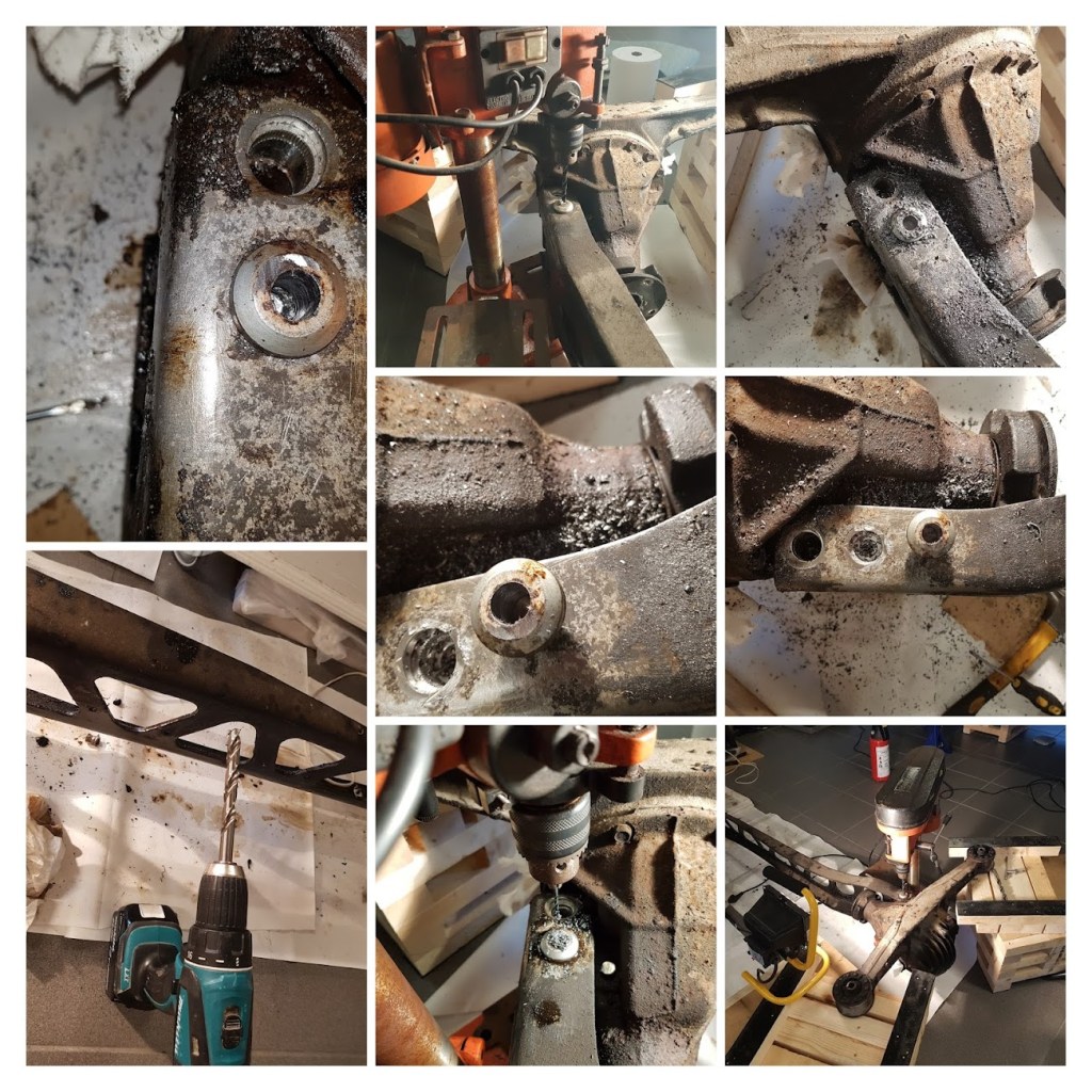
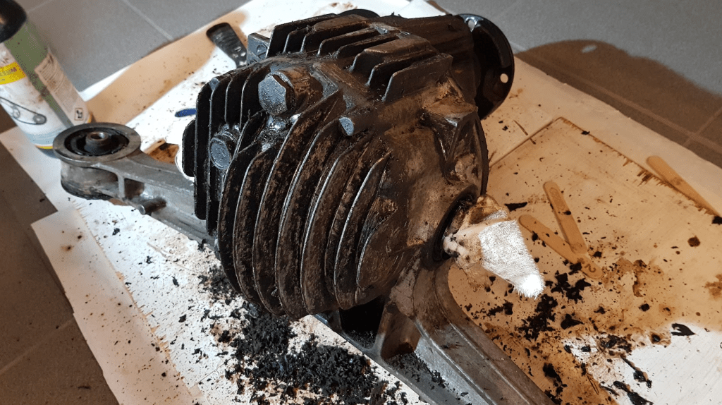
It was all fun and games until the differential had to come out. Why bother I hear you ask, but replacing all bushings means replacing all bushings: including the two fist sized ones where the differential meets the rear subframe. Now, the differential on an MX5, is hung from the rear subframe and also attaches to a long-ass U-shaped steel bracket called the PPF (Power Plant Frame) that is fixed to the gearbox in the other end creating a solid drivetrain. The PPF and diff are lightly held together by 2 10/12mm odd shaped (well, one of them, the other is pretty normal) bolts that’s been torqued to 120Nm from birth. Add to that 20 odd years of hot and cold cycles, road grime, salt etc. and you have a perfect recipe for bolts not wanting to come out. I had a long chat with the rearmost one and that one came out with out too much trouble. The other one however, now that’s another story. <It would be funny to quote Marsellus Wallace here, but I’m not very black, so I can’t> Penetrating rust remover sprayed on top letting that soak until it came out the bottom, battery powered impact gun, air powered ditto, breaker bar with 2.5m extension, plenty of heat etc. Nothing made any impression. So the only option was to remove the diff and PPF together – that was easy(‘ish):
The floor had just been redone (seriously, it had) – it was pristine when the MX5 entered.
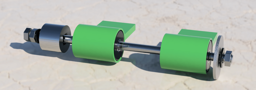
Now, had this been easy, one would cut the head off the bolt on the bottom and then just start whacking it repeatedly with the biggest hammer in your toolbox since the nut in the top is knurled and pushed into the PPF. The only problem is, that the bolt might be 12mm in the bottom but only 10 where it meets the nut. So the only way is to clear the threads in the nut – and THEN start banging with the biggest hammer in the toolbox. I’ll let the pictures tell the rest, but it required a pillar drill and an angle grinder:
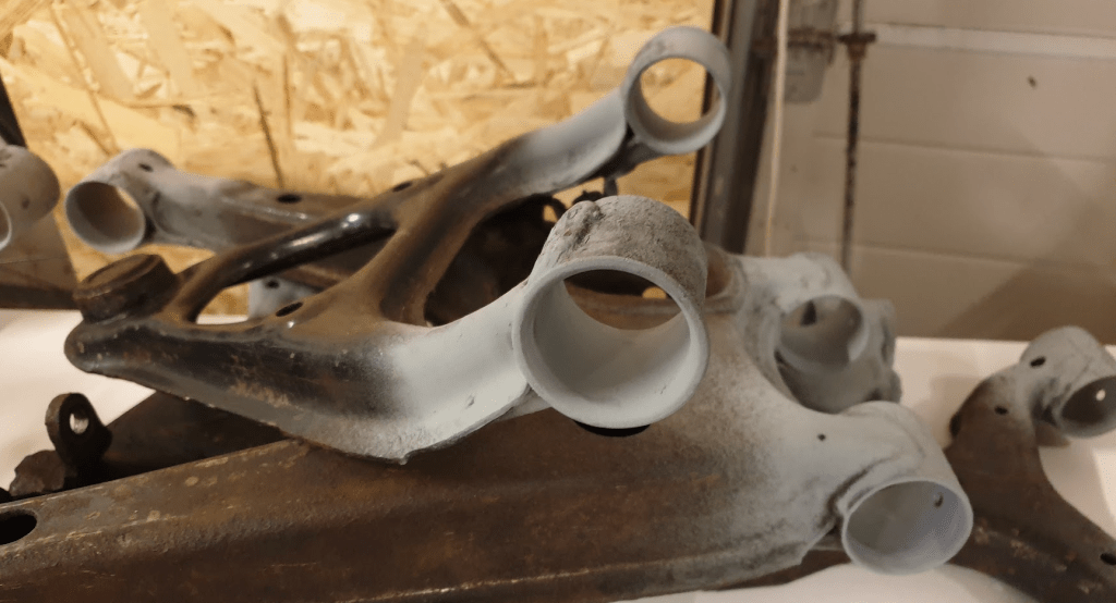
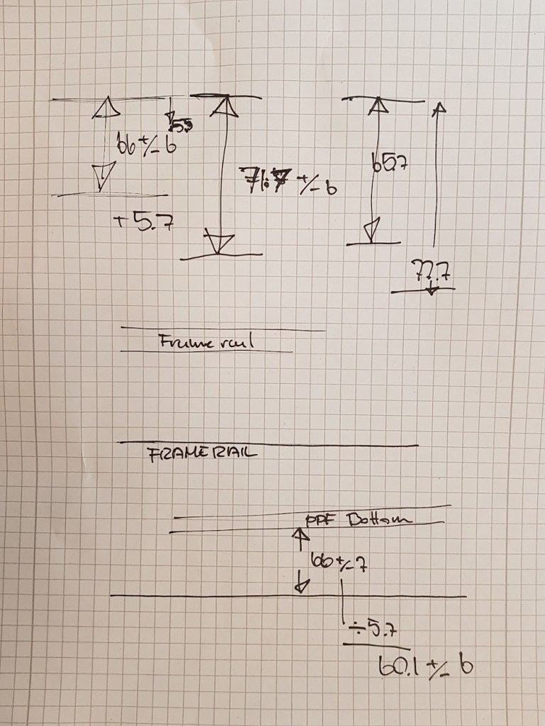
Took the best part of two evenings…Many yucks….. Compare this to the first picture…..Control arm – they all looked like shit this…And eventually to this – cleaned up and a quick shot of zinc primer. Plan is to have them soda or sand blasted and powder coated green, because, why not. PPF cleaned up nicely.Diff and PPF going back in with cleaned up/zinc coated retainers. Unless you suffer from serious self loathing or just want to please your inner masochist, seriously, get a buddy over to help with this – it’s a royal pain in the ass trying to get the rear to line up, then the front, again, lather-rinse-repeat. And remember to align the PPF / gearbox when the PPF and diff is in place. I followed this guide: https://www.mx5nutz.com/threads/how-to-align-your-gearbox-and-ppf-fix-gearbox-lash.55139/ (opens in new tab – don’t say I didn’t warn you!)My notes. I’m a very visual type of guy ( :
Bushing removal – what I learned:
The control arm bushings are actually a piece of piss to get out once you find the hack. Search the web and you and find all sorts of ways to get them out. The blowtorch way burning them seems especially fun and healthy, both for you and the planet – but since our garage is actually part of the house, that idea was dropped like a red headed step child.
In the end, the only thing I used was a 1m threaded rod, a big socket that fit inside the tube where the bushing lives, and big spacer that won’t fit in the tube where the bushing lives, a couple of smaller spacers and 3 10mm nuts – and the most import thing: a little heat! I’m not talking gas powered blowtorch red-hot metal heat. I used a simple 1600w Bosch heat gun that you would use to strip paint off an old door (Why I bought it back in the days actually).
I don’t have any pictures of the setup – I was too busy swearing to take any, but this should give you an idea of what each end should look like:
Now, I used the setup without heat for the first couple of bushings, but it was hard work. They are in there, and they are in there good. I managed to bend one of the rear upper control arms doing it like thisnote:1, that’s the kind of “in there” they are. Until you apply heat that is. They soften up completely, and if you’ve got thick skinned fingers, I bet you could (DO NOT TRY THIS BECAUSE I SAID SO – shit it still shit hot!) push them out with your thumbs.
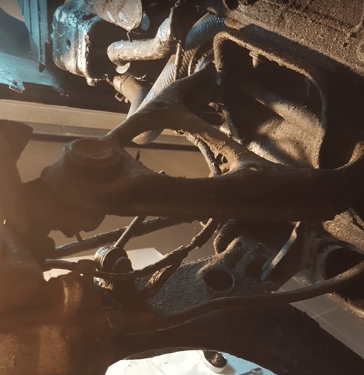
Apart from them having been in there for 20 years and having created an almost unbreakable bond with the control arms, deposits of rust isn’t helping:
When a rubber bushing is hardened from 20 years of hot/cold cycles, that isn’t going to help them getting them out.
note:1 Yes. I actually am THAT smart. I could tell it was going somewhere bad, but still kept applying pressure. (I reversed the mishap with the standard MX5 jack between the legs of the control arm, so there!)
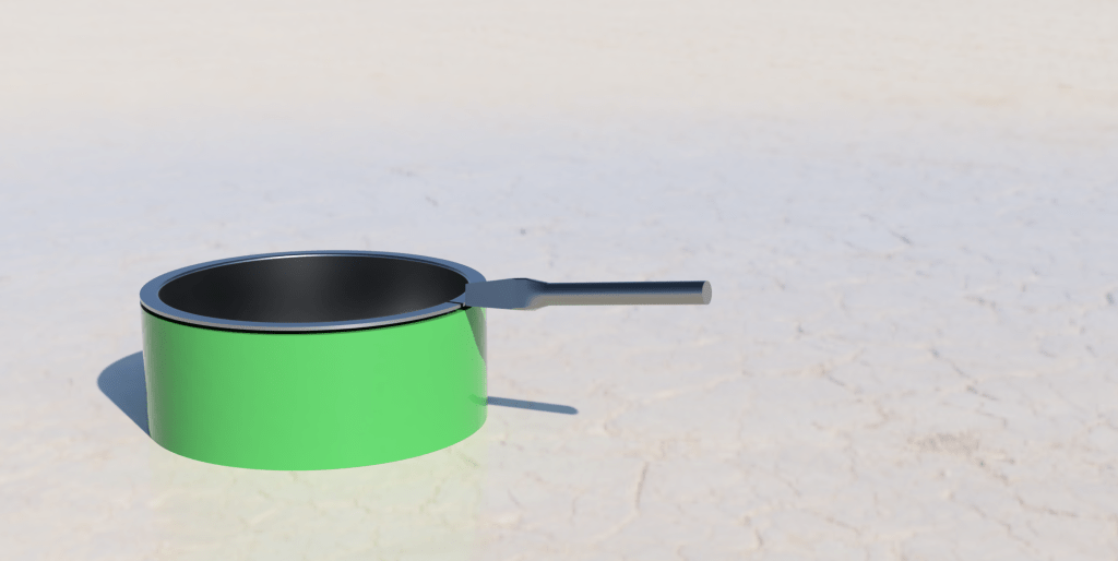
Differential Bushings. Not as much as piece of piss as I only had two to practice on, but once the solution is presented: stupid easy. As with the control arm bushings, many methods are available from Google. Common thing is, get rid of the rubber material, then get to work on the metal shell. Now, since fire is definitely out, I started by drilling as many holes as I could in the rubber. Don’t worry about scratching the metal shell, it’s coming out and going in the trash. Then the trusty jigsaw and went to work (again) on the remaining rubber <I just realized the Marsellus Wallace quote with the pliers and the blow torch would work equally fine here. I’m still not black though>
When you search for solutions on how to get the metal shell out, the one that inspired me, and I thought sounded like a good idea, was again using the jigsaw to cut two lines in the shell leaving you with two halves to pry out, so I started doing that, but here comes the monumental shocker: There is already a cut all the way down in the shell, no need to use the jigsaw. You just have to look for it because it’s thin and it’s covered in dirt and underbody protection and 20 years worth of road grime. But it’s there. So once most of the rubber is out, find the cut the in the shell, get a flat headed screwdriver and a hammer and you can easily, and I mean easily, no need to go medieval on it, bend in the first corner, then with a little well aimed violence and a pair of pliers <there it is again> getting the shell out is no problem at all – a tiny but of persuasion is all that’s needed.
This should give you an idea – start by getting a corner loosened and work your way around with a chisel, flat head screwdriver or your nails if you’re a man’s man (I’m not, screwdriver and hammer thank you very much)
I’m not a brave man. With enough time to contemplate, think things over, then check and re-check, I’m pretty sure I can do most anything. My Nemesis though, is the black magic known as electrickery (seems ideal coming from someone who’s looking at doing a custom loom himself) – It’s not too bad when we’re dealing with low amps and power supplies with fail safe and short circuit protection. But when it comes to 12V automotive electricity and batteries able to supply many many amps and set stuff on fire and explode and spray gallons of corrosive acid all over the neighborhood, I’m out.
Having pushed the elephant in the glass room around in front of me for long enough, I was running out of excuses and entries on my To-Do list:
All Hoses checked and tightened for the nth time
4 liters of 10w40 poured into the engine (3.8 with 200ml on top for filter)
Most of 1 quart in the diff
Most of 2 quarts in the gearbox
Basic electronic check (connect battery and see that nothing explodes) Note:1
etc.etc.etc
all done, no more excuses – it was time.
So started adding water to the cooling system. (It takes 6 liters or thereabouts). Got 3 liters in there when I noticed the sound of trickling water?. DAFUQ? I mean, I’d always wanted a little water fountain thing in the garden for the birds – definitely not in the garage. So look beneath the car as best as one can when it’s finally on the floor. Most of my precious water after the first 1 and a half liter or so is on the ground. Great : ( Did I miss tightening a hose, are my clamps too weak. I mean, I didn’t replace all the cheapo hose clamps with T- types to have water, that’s not even under pressure yet, piss out…
Nothing to do but raise the car again so I can get beneath it and have a quick look. I can see where it’s coming from – the inlet on the water pump distributor thingy (I had to Google that too). So loosen clamp, re-seat, re-tighten, re-try. Same shit. Car up on blocks again, clamps all the way off, hose off. *Looks at inlet pipe*… “That doesn’t look very good”. Out comes the impact gun armed with a 12mm socket. As Adam Savage would’ve would’ve put it: “There’s your problem right there“…. fuck…
Hmmm. I could probably do a hack job with some surplus hose to see if everything is ok, but I really don’t want to so a new part has been ordered with new gaskets. (Kauf oder sterben)
However – Being determined now that I’d gotten myself this far, I did turn the key all the way, and lo and behold: she started right up. Only let it run for a few seconds, but it started and it didn’t catch fire and I didn’t burn down the garage. Fucking YAY for me and my (lack of) skills \o/
Note:1 Of course I’d already done this with a 10A lab supply, but that doesn’t mean connecting the actual battery is not scary.
Now, if you have a Major in Geometry, this will seem easy. If you, like me, don’t have one of those fancy-smancy titles, then you’ll need to dig deep (not that deep really, but I definitely could’ve used an ELI5 on some of the things that now seems logical).
Day-Z – one of our two little helpers not helping.
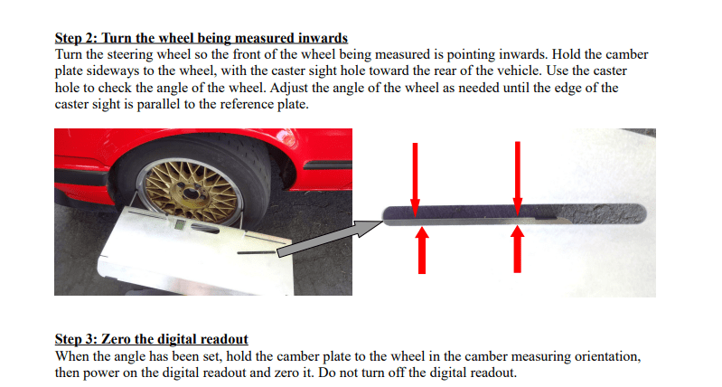
I started out by following Donut Media’s Zach Jobe in his “Alignment Explained (+ DIY guide)” – not going to embed it here, go there, click Like and support the Donut Media guys as they do awesome stuff. However, I had to do a couple of things differently – not sure if this is me doing something wrong or ass backwards- or it’s Zach jumping the lowest part of the fence (or maybe the gate was open). I can only tell you what worked for me.
Last things fucking first: Since I’d disassembled everything without taking notes, once kinda reassembled, I had an MX5 that was completely bent out of shape out of anything resembling alignment. The different guides on the net all says to write down the settings before taking shit apart. Well, do I look stupid to you?. I don’t need to do that, this is easy right? (Besides, everything was covered in sticky black goo, so getting any form of readings would be guesswork at best, so there!). Nowhere does it say how to start out if you didn’t write your settings down and used those as base settings, so I did the only logical thing (after many hours of contemplating and many “hmmms” and “one could maybe also”‘s) and set everything as close to zero without spending a million hours on it. Toe and camber as a priority.
Caster (front only):
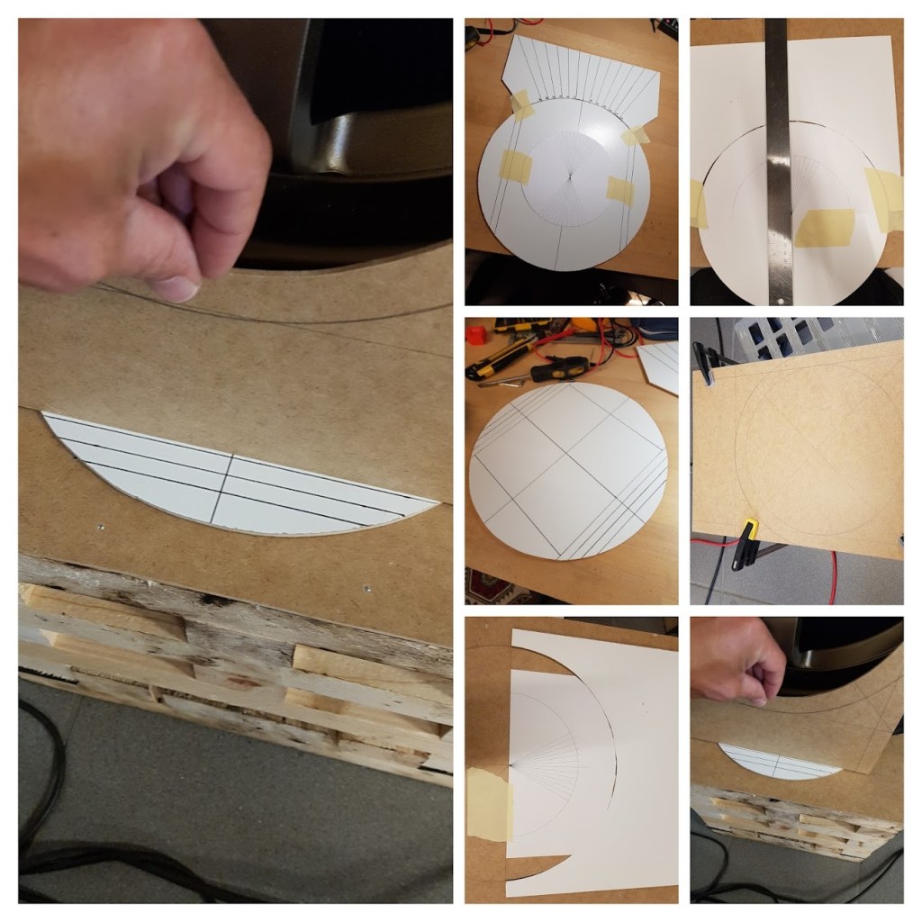
MUY IMPORTANTE! Here’s a thing I found out when using the turning plates for measuring, and this may or may not work for you depending on your wheels: I would get the same number if I used the Tenhulzen plate to measure the angle with the angle finder in the plate like this:
or if I just placed the angle finder on the center cap.
As Zach correctly (because: geometry) says in the video, you start out by adjusting caster. This is not too complicated once you find out what you’re doing. If you start with the left front wheel (front, of course, there’s not caster in the rear), you turn it 20 degrees to the right, zero out your angle finder on the wheel, then turn the wheel 40 degrees to the left and measure the angle again and multiply by 2. That’s your caster number – simples right? ¯\_(ツ)_/¯
Aaaand Action: In a whim, whip up a set of turning plates a-la Zach, turn the wheel to one side, zero out, turn to the other side, measure angle again, adjust and Bob’s Your Uncle right?. Not quite for this old dog:
Trying and trying and trying. Then stop, you look like an idiot. I plowed on regardless.
After I made the first set of turning plates, I simply didn’t trust the numbers I got when measuring the angle. No matter how many times I tried, re-setting the plates, turning this way then to other. It was no good. I could not get any consistent numbers. So, set number 2 was made. This time larger with more care taken and more lines to align them beneath the wheel. Still no fucking good. I still could not get the same number two times in a row when repeating the procedure (lather-rinse-repeat FFS). So on to phase two: Now, the first thing I did when I bought the MX5, before I found Zach actually, was buy a set of the Tenhulzen toe plates with angle finder and 2 x tape measure (which were immediately set on fire and thrown to the ground as they were inches onlyNote:1) as I knew I’d be doing alignment myself (“Be prepared, that’s my motto”). They can also be used when setting caster so out come the instructions from Tenhulzen. But because my car was on blocks and not on the ground as in the instruction video and pamphlet, I had to get creative with painters tape:
This was just the beginning, didn’t take any more photos.
But, same same as with the turning plates. I still couldn’t get consistent results and this was seriously starting to piss me off! Sitting in grandmas chair in the garage (NO, she doesn’t live in the garage, she’s dead, we just got the chair) pondering how to best set this thing on fire without burning down the house, I spotted, in the outbox destined for scrap, an old Ikea frame with a checkered background and Hey!, that odd moment of clarity you experience once in a blue moon.
As simple as copying the angle from the Tenhulzen plate, doubling it and using it for the pointy end of an arrow and you get this:
Used half of the backing plate as base for the checkered sheet and the other half for the arrow thingy. The angle of the “arrow” is taken from the Tenhulzen toe plate and doubled (40 degree). Now THAT requires a “Simples” ¯\_(ツ)_/¯
Instructions should not be necessary but: Make sure the checkered board is aligned with the wheel (use a ruler from the edge of the wheel to a line on the board) before you secure it in place, put the arrow on top, turn the wheel until the first of the angled sides lines up with the board, zero out your angle finder, turn the wheel the other way so the other angled side of the arrow lines up, measure the angle of the wheel, multiply by 2 and there’s your caster. BOOM: Headshot. With this, I could get consistent numbers 10 times out of ten!.
Then it was just a matter of adjusting the rear bolt holding the lower control arm until you get the desired number. I think Zach mentions in the “Answering Subscriber Questions (50th Ep Special)” episode of Moneypit, that he would’ve gone higher with the caster, so I went with 3 (that makes the caster number 6 – multiple by 2 remember?). (He also mentions that had he known then what he knows now, he would’ve outsourced the alignment… I’m thick skulled, so I didn’t but having learned a new skillset makes it well worth it).
Camber – Front:
But first, why I think Zach said something wrong:
Now: There is one place where I’m positive I’m right and Mr. Jobe is doing something wrong, purely based on simple geometry. When he starts working on setting the camber, he tells you, that if the car is on an uneven surface (which makes matters worse actually), you can zero out your angle finder on the block the wheel is sitting on: Here’s why I think that’s a big-ass fucking no-no:
When you zero out your angle finder on the block the wheel is sitting on, you’re zero’ing it our relative to that particular place on your uneven floor, not relative to the car (which is what you want: You want 1.5 degree negative camber relative to the car, not to a single spot on the floor). Let’s put some numbers on my ramblings:
If your blocks are 35×35 cm (WxD) and 30 cm tall (could be 2 meters, this number is irrelevant) and it’s tilted, because your floor is uneven, by say, .3 degree left to right, that’s means one side of the block sits 1.833 mm higher than the other. This then means, that if you use this block to zero out your angle finder, it’s zero’ed at .3 degree, relative to that specific place on the floor, not relative to the car which is what you need/want. If you instead use a straight bar that goes from the left block to the right, if you include the height difference left to right on the tilted block, you get a zero’ed out value of 0.07 degree instead, and this being relative to the car, not to a single point on the ground.
The numbers above could reflect a real word scenario, but they’re too small to do well on illustrations however, so let’s turn the numbers up to 11 (Why not just make 10 louder) so we can get something visual (I said it before, I’m a visual guy). This time we tilt the offending block by 2 degree instead of 0.3, now the difference between the left and right side of the block is 12.15 mm. If we use the bar covering both blocks, we’d instead get a reading of .43 degree and not 2. Obviously the tires being flexible would mitigate some of the unevenness caused by the 2 degree tilt in the right block, so let’s say that take out 2/3rds of the .43 degree, that leaves the car with a tilt of .14(‘ish) degree which would leave you with a real world camber setting of 1.36 if you’re aiming for 1.5 degree negative – if you went with the angle finder zeroed out on the 2 degree tilted block, you’d end up trying to push around 3.3 degree negative once the car is on an even surface (pretty sure my calculations are correct).
The top of the two angle finders to the right is zero’ed out on the bar spanning both blocks, the bottom one on the tilted block as Zach suggests – you can see the obvious problem: Garbage In, Garbage Out. Sorry Zach, couldn’t help it 😉
With that out of the way, on the front, it’s a question of adjusting the front bolt holding the lower control arm until you get the desired number. Mine is an NB and they’re not quite as willing to go as high as NAs. I’ve seen posts where people couldn’t get them above 1.5 degree negative. I was able to get mine to 2 on both sides.
20210928: This will be updated once winter is here and it’s back on the blocks. The above information is not wrong, but there might be a twist that I (and obviously Zach too) missed by not reading the factory manual in the first place! (Did you know, just 4 hours of debugging can save you 20 minutes of reading the actual manual?)
Toe – Rear:
Why not set the Camber in the rear after the front as Zach does in the video?. Because the official Mazda manual says so
and because I had a great time figuring out what was going on blindly following Zach!.
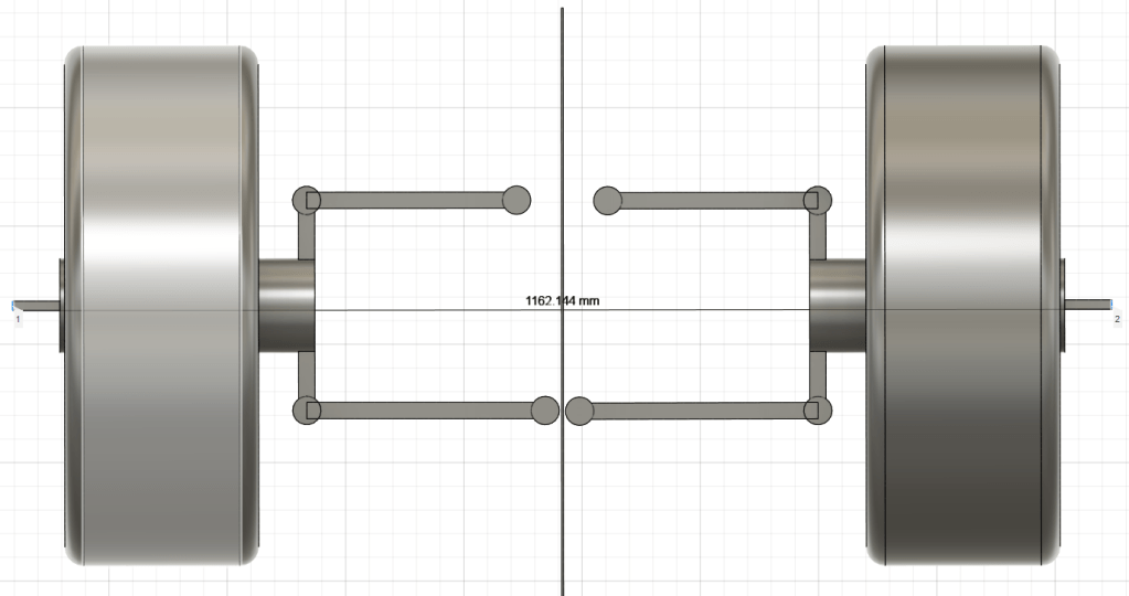
Now. Since I don’t have a fully fledged shop with friggin’ lasers for adjustment, I did this using the string box. Zach explains how to make on and set it up better (and faster than I can). There is a small note for those of you starting from scratch: If the camber on your rear wheels is out of sync, so will your string box be. Here’s the rear wheels with 0 degree camber on both sides, meaning your string box will be straight:
But look how much out of line your string box will be if we add just 1 degree of camber to the left wheel:
That’s 2+ mm which means your string box is now all fuxxored and all the toe readings you’ll get will be out of whack (so says the youth of today) And that’s with 1 (one) degree. So make sure your rear wheel camber is ballpark equal before you start building your string box. Same goes with the front, but those should be aligned by now.
With the box in place, there’s not much to adjusting toe in the rear. Turn the front most adjustment bolt outwards, you adjust towards toe-out, turn the rear most adjustment bolt outwards, you adjust towards toe-in. Turn the front most adjustment bolt inwards, you adjust towards toe-in, and finally, turn the rear most adjustment bolt inwards and you adjust towards toe-out. I did both at the same time trying to get the numbers as equal as possible (I don’t want to think about the number of times I got down on the floor, adjusted, got up, measured front and rear on the wheel, then lather-rinse-repeat ad nauseum). I ended up with -0.77 mm in one side and -0.84 mm on the other.
Camber – Rear
Simples, adjust front and rear bolts outwards the same amount at the same time for moving towards (or adding more) negative camber, inwards for reducing negative or moving towards positive (we don’t want that).
Now, I did say simples, and it is, it just takes a lot of tries to get it spot on. I went with 2 degree negative to match the front.
Job jobbed, as the kids say today.
I think that’s it basically and concludes my learnings for doing your own alignment. It’s a pain in the proverbial behind sometimes until you figure out the ins and outs and do’s and don’ts.
Note:1 on the Imperial System: Because: “Does this look like 5/8’s?”; “Naaah. That’s more like 7/16th’s” makes about as much sense as:
Fucks sake it’s stupid (apologies to all who find this logical and thinks the metric system is the work of the devil. You’re still wrong though)….
Convert the more or less stock MX5 to something resembling Kento’s supercharged NB worthy of taking to the Nürburgring, on a budget (which was looked at, considered, and then almost immediately thrown out the window)
The list started as:
Wheels / Tires
Coil overs
Bushings all around
Rollbar (because race car)
Retro 3 spoke steering wheel (because race car)
Bucket seats (because race car)
Basic refresh (hoses, plugs, fluids, pads)
and then throw away anything that didn’t make it stop, turn or go – all while keeping it street legal. The Nürburgring is a public road, so unless it’s a closed track day, your car has to be registered and inspected. Also, the Ring is about 750 km from our garage door and we still need to get there.
But as I’m a “Can’t leave well enough alone” and “While I’m there” kinda guy, that list, of course, turned out to be more than a bit short. So what started as a quick do-up turned into the car being on stands for 10 months.
Eventually, there’ll be a post summarizing things – no idea when this will happen.
2021-08-25: One thing I need to point out, apart from prepping this for the Ring so it doesn’t actually kill me when we get there: It’s also a chance to learn something new, so I will be, to the best of my abilities, doing everything myself. If I get lost or my flabber gets completely ghasted along the way, I hope Google or YouTube will be able to sort me. I’ve done plenty of work on bikes, but this will be my first rodeo in the car world (This is also not true, I’ve changed pads and discs on the up!)
First picture after having returned home. 170km in pissing rain with dad in the support vehicle (our VW up!) bringing up the rear. Looking back, she’s more than a little sad looking. Wheels too big. Ride height like a truck. Yellowed headlights – the list is long. Still, she’s fairly healthy, plenty of bills for maintenance, so should be a good starting point.